GSM (Global System for Mobile Communications) is a Digital Wireless Technology used for cell phone in the world that is, it is a cellular technology used for transmitting mobile voice and data services. It was developed by the European companies.
Features Of GSM
- It is 2G Technology
GSM is a circuit-switched technology
Uses GMSK [Gaussian Minimum Shift Keying] Modulation
- It supports FDMA & TDMA
- It uses SIM card so u can easily switch your SIM card between phones
- International roaming is easier on a GSM network
- In GSM every user requires a separate frequency channel for communication
- GSM accounts for 80% of total mobile phone technologies market
- The Frequency Band(range) in GSM
The frequency of the carrier is very important, because it determines the Size, power, efficiency of your mobile phones.

- It supports FDMA & TDMA as Multiple Access Techniques


20:35 |
Posted in
Digital Communication System
|
Read More »
Radio signals are transmitted through electromagnetic waves, also called radio waves, in radio communication system. The radio waves have a wide frequency range starting from a few ten kilo Hertz (kHz) to several thousand Mega Hertz (MHz). This wide range frequencies is called the radio spectrum or RF spectrum.
The RF spectrum is classified according to the applications of the spectrum in different service areas. The classification of the RF spectrum is given in below table along with the associated applications in communication system.

16:10 |
Posted in
Communication Basics,
Digital Communication System
|
Read More »
Microwave is a kind of electromagnetic wave. In a broad sense, the microwave frequency range is from 300 MHz to 300 GHz. But In microwave communication, the frequency range is generally from 3 GHz to 30 GHz.

Concept of Digital Microwave Communication
Digital microwave communication is a way of transmitting digital information in atmosphere through microwave or radio frequency (RF).
Microwave communication refers to the communication that use microwave as carrier.
Digital microwave communication refers to the microwave communication that adopts the digital modulation.
The baseband signal is modulated to intermediate frequency (IF) first . Then the intermediate frequency is converted into the microwave frequency.
The baseband signal can also be modulated directly to microwave frequency, but only phase shift keying (PSK) modulation method is applicable.
16:01 |
Posted in
Digital Communication System
|
Read More »
Multiplexing
Multiplexing is the set of techniques that allows the simultaneous transmission of multiple signals across a single data link.
Multiple Access
If the physical links are shared by more than two nodes/users, it is said to be Multiple Access.
Categories of Multiplexing
a. Frequency Division Multiplexing (FDM)
b. Time Division Multiplexing (TDM)
c. Wave Division Multiplexing (WDM)
Categories of Multiple Access Methods
a.Frequency Division Multiple Access (FDMA) - flexible and simple
b.Time Division Multiple Access (TDMA) - popular
c.Code Division Multiple Access (CDMA Spread Spectrum) - highly secure
15:42 |
Posted in
Digital Communication System
|
Read More »
Why do we need Multiplexing technique?
In communication, under the simplest conditions, a medium can carry only one signal at any moment in time.For multiple signals to share one medium, the medium must somehow be divided, giving each signal a portion of the total bandwidth. This is where the concept of Multiplexing comes!
Multiplexing means “sharing a medium”. It is a form of data transmission in which one communication channel carries several transmissions at the same time. In simple words, the method of dividing a single channel into many channels so that a number of independent signals may be transmitted on it is known as Multiplexing.

Multiplexing techniques can be divided into two basic categories:
Frequency Division Multiplexing-FDM
Time Division Multiplexing-TDM
Frequency Division Multiplexing-FDM
In FDM the available bandwidth is divided into a number of smaller independent logical channels with each channel having a small bandwidth. It assigns “frequency ranges” to each “user” or “signal” on a medium. Thus, all signals are transmitted at the same time, each using different frequencies.The method of using a number of carrier frequencies, each of which is modulated by an independent signal is in fact frequency division multiplexing.

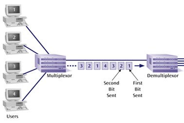
Time Division Multiplexing-TDM
In TDM, sharing is accomplished by dividing available “transmission time” on a medium/channel among users.
Each user of the channel is allotted a small time interval during which he transmits a message. Total time available in the channel is divided, and each user is allocated a time slice. In TDM, users send message sequentially one after another. Each user can use the full channel bandwidth during the period he has control over the channel.

20:13 |
Posted in
Communication Basics,
Digital Communication System,
FDM,
TDM
|
Read More »

The term Multiplexing means "sharing of a resource/medium" .Resource could be time, frequency, space or any physical medium .Multiplexer is a communication device that multiplexes (combines) several signals for transmission over a single medium.
It helps different sources of data to use a single medium for transmitting their data.Basically the aim is to share an expensive resource
In more simple words, Multiplexer also called as Mux is a device that selects one of several analog or digital input signals and forwards the selected input into a single line.A multiplexer of 2^n inputs has n select lines, which are used to select which input line to send to the output.
A device that performs the reverse process is called a Demultiplexer (DEMUX).
Follow this tutorial for more understanding of Multiplexer
The Operation of a Multiplexer/Demultiplexer Circuit
07:03 |
Posted in
Digital Communication System,
Digital Electronics
|
Read More »
Environmental interference and physical defects in the communication medium can cause random bit errors during data transmission. Channel coding also known as Error coding is a method of detecting and correcting these errors to ensure that information is transferred from its source to its destination reliably.
The idea behind channel coding is, to make the data more secure and error free. Channel Coding is done to ensure that the signal transmitted is recovered with very low probability of error at the destination. You can think channel coding as a “Security guard” for data .
What happens If Channel coding is not used?
If data is transmitted without channel coding ,and an error occurs in data , the receiver will inform the transmitter that an error has occurred in data, therefore transmit it again.Transmitter will have to retransmit the whole data ! A question may arise in your mind that, incase of error, data will be retransmitted so, what’s the need of using channel coding?
The reason is, if transmitter retransmits the whole data definitely there will be wasteage of power,and delay in communication. Therefore to avoid these factors it is necessary to implement channel coding.
In channel coding extra bits are added along with actual data bits. These extra bits are termed as “Redundant bits” because they actually cause redundancy in data. They ensure minimal or no error.
Error coding uses mathematical formulas to encode data bits at the transmitter or source into longer bits for transmission. The "coded data " is then decoded at the destination to retrieve the information. These bits help the the destination or receiver to determine if the communication medium introduced errors, if yes correct them so that the data need not be retransmitted.
Error coding is used in satellite and deep space communications, network communications, cellular telephone networks, magnetic and optical data storage media, and almost any other form of digital data communication.
20:09 |
Posted in
Communication Basics,
Digital Communication System
|
Read More »
When data is transmitted to its destination over a communication channel there is a possibility of errors being introduced into the the data. In digital communication performance of the system is assessed by a term called as bit error rate, BER. BER is also known by the term Probability of Error.
In simple words, it is actually the ratio of number of bits in error to the total number of bits transmitted.
BER = Bits in Error/Total Number of Bit transmitted
For instance, If 10 bits were transmitted, and 5 bits get in error,then :
BER=5/10
=0.2
In BER curve if a value is mentioned, say 0.01, it means ,out of 100 transmitted bits, 1 bit got error [1/100=0.01]
Example:
Let's consider an example, assume a transmitted bit sequence:
0 1 1 0 0 0 1 0 1 1
and the following received bit sequence:
0 0 1 0 1 0 1 0 0 1,
The number of bit errors (the underlined bits) is in this case 3. The BER is 3 incorrect bits divided by 10 transmittedbits, resulting in a BER of 0.3 or 30%.
22:13 |
Posted in
Bit Error Rate,
Communication Basics,
Digital Communication System
|
Read More »
Frequency Division Multiplexing (FDM)
 In FDM system, signals from multiple users/transmitters are transmitted simultaneously (at the same time slot) over multiple frequencies. That is each user is assigned a different frequency for communication. Each frequency range is called as sub-carrier, n it is modulated separately by different data stream, that is there are different sources of data (users/transmitters) for each subcarrier frequency. A spacing (guard band) is placed between sub-carriers to avoid signal overlap.
Orthogonal Frequency Division Multiplexing (OFDM)

Like FDM, OFDM also uses multiple sub-carriers but the sub-carriers are closely spaced to each other without causing interference, removing guard bands between adjacent sub-carriers. This is possible because the frequencies (sub-carriers) are orthogonal. In OFDM multiple subcarriers are modulated by single source of data. If I am a transmitter, n using OFDM technique, my data will be modulated by multiple subcarrier frequencies , instead of single carrier frequency ,as it happens in normal modulation .if I assume that 3 subcarriers are being used for modulation so, they will modulate the data of just one Transmitter ,unlike FDM where 3 frequencies will b used to modulate three different sources of data (three transmitters).
In an OFDM system, a very high rate data stream is divided into multiple parallel low rate data streams. Each smaller data stream is then mapped to individual data sub-carrier and modulated using some sorts of PSK or QAM modulation . let’s assume that I have a high rate data stream, X=[abcdefghi] ,
I divide it into three low rate data streams [p=abc, q=def, r=ghi ].Assume that there are three sub-carrier frequencies: f1,f2 n f3
Each low data rate stream will be modulated individually by each sub-carrier,that is data stream ‘p’ will be modulated by carrier f1, data stream ‘q’ by f2 n similarly data stream ‘r’ by f3 and finally all are combined.If it were FDM technique ,the data stream X would have been modulated by a single carrier frequency instead of multiple carriers.Therefor OFDM is called as multi-carrier modulation
Orthogonal Frequency Division Multiple Access (OFDMA)
 Like OFDM, OFDMA employs multiple closely spaced sub-carriers, but the sub-carriers are further divided into groups of sub-carriers. Each group is named a sub-channel, different colors in figure show a different sub channel. The sub-carriers that form a sub-channel need not be adjacent. Sub-channels actually used for multiple access (multi users communication). Each sub-channel consists of multiple carrier frequencies. For instance I have two sub-channels, S1 n S2. S1 has carrier frequencies f1 ,f2,f3, and S2 has carrier frequencies, f4,f5, n f6 . sub-channel 1 will b used to entertain one user/transmitter and sub-channel 2 will b used by another user/transmitter.
05:48 |
Posted in
Communication Basics,
Digital Communication System,
FDM,
OFDM,
OFDMA
|
Read More »
Firstly, what do we mean by digital modulation? Typically the objective of a digital communication system is to transport digital data between two or more nodes. In radio communications this is usually achieved by adjusting a physical characteristic of a sinusoidal carrier, either the frequency, phase, amplitude. This is performed in real systems with a modulator at the transmitting end to impose the physical change to the carrier and a demodulator at the receiving end to detect the resultant modulation on reception. We begin our discussion by three basic types of digital modulations:
- ASK [Amplitude Shift Keying]
- FSK [Frequency Shift Keying]
- PSK [Phase Shift Keying]
All of these techniques vary the parameter of a sinosoid to represent the information we wish to transmit.
A sinusoid has three parameters that can be varied, these are amplitude ,phase and frequency.
- In FSK we change the frequency in response to information. One particular frequency for ‘1’ and another frequency for ‘0’.

- In PSK, we change the phase of carrier signal to indicate information.

23:56 |
Posted in
BASIC ELECTRONICS,
Communication Basics,
Digital Communication System,
Digital Modulation,
How Stuff Works?
|
Read More »
The basic building blocks involved in digital communication system can be seen in the figure. Some block shown above might seem strange for the newbies. Source Coding is the process of compressing the data efficiently. In other words, source coding is the process of optimizing the length of data. An example of this can be a surveillance system. It is useless to send the whole background of the image when a motion is detected. Source coding is thereby used to send only that portion of a frame which is being changed and not the useless information in terms of the whole background. Another example of this could be the transmission of English Text. We know that the probability of occurrence of vowels i-e a,e,i,o,u is more than the other alphabets thereby giving a clue to compress the English Text in terms of bits transmitted.
After that comes the Channel Coding. For a layman, it can be referred to as opposite of Source Coding in term of process. Channel coding involves the addition of redundant bits to a message signal that will make up for the errors. This involves the identification and as well as the correction of errors, if any. Hamming code it the best example of Channel Coding. Modulation and Demodulation needs another post for discussion which will be discussed later.
More to Follow!!
18:01 |
Posted in
BASIC ELECTRONICS,
Block Diagrams,
Digital Communication System
|
Read More »


