8051/AT89S52 based RPM meter using Mouse Encoder
Problem Definition:
The task at hand was to create an RPM meter using AT89S52 microcontroller that displays the generated RPM count.
Life Cycle of a Microcontroller Project:
It was important for us to have a general idea of the steps that are followed to realize a project, from the very beginning of an idea to the very end of project completion.
The figure below shows the steps that were followed by us after we settled on the choice of our project in the 'brain storming' part. It was imperative for us to imagine how it could be implemented from the hardware point of view, before we passed on to the programming phase, because programming is much more flexible than the hardware design. In other words, we started by designing the hardware, then worked on the programming while taking in consideration the eventual constraints imposed by the hardware design.

The hardware design includes all the aspects of the electronic connections between Microcontroller and other devices, like the compatibility of the voltage levels, or the required number of pins, etc.
After completion of the hardware, we diverted our attention towards the programming phase. When the first program was developed, the HEX file was generated by the compiler, and was sent to the 'program memory' of the microcontroller. Eventual errors were corrected and performance was enhanced gradually, taking in account the famous rule which states that
“Any project never works the first time; at least it does not work as you expect it to do.”
Hardware Design:
Click to enlarge.

Module 1 – Devices:
This section contains the devices that are connected externally. In our case there is only a small DC motor of rating 5V. It is basically used to drive the mouse encoder that generates the revolutions.
Module 2 – Input:
This section implements a small ball mouse rotary encoder that is being driven by the DC motor. The amount of revolutions depends upon how fast the DC motor spins the encoder. These analog revolutions result in a difference in voltage at the input of the Comparator IC LM324 that basically compares and converts the voltage difference into pulses of 0’s and 1’s. This data is fed into the microcontroller 89S52 that calculates the RPM Count.
Module 3 – Output:
The generated RPM needs to be displayed on and output device. But before that it is fed to the Buffer IC 74LS245 by the microcontroller that boosts the current. It is further connected to the PC screen via parallel port interfacing.
Each of the above component will be discussed in different sections of the blog. Lets take a quick overview of Software execution of the above project.
Component Discussion
The RPM meter project consists of the following main components. Click to see the details please.
SOFTWARE DESIGN:
This section deals with the software aspects of out project. The coding required in this project was a mixture of C languae and Assembly language. For that we used the Turbo C and KEIL uVision Softwares.
From the C program to the machine language:
The C source code is very high level language, meaning that it is far from being at the base level of the machine language that can be executed by a processor. This machine language is basically just zero's and one's and is written in Hexadecimal format, that why they are called HEX files.There are several types of HEX files.
Diagram below shows that to convert a C program to machine language, it takes several steps depending on the tool that is used, however, the main idea is to produce a HEX file at the end. This HEX file will be then transferred to the hardware to write every byte of data at the appropriate place in the EEPROM of the 89S52.

Program Flow Chart
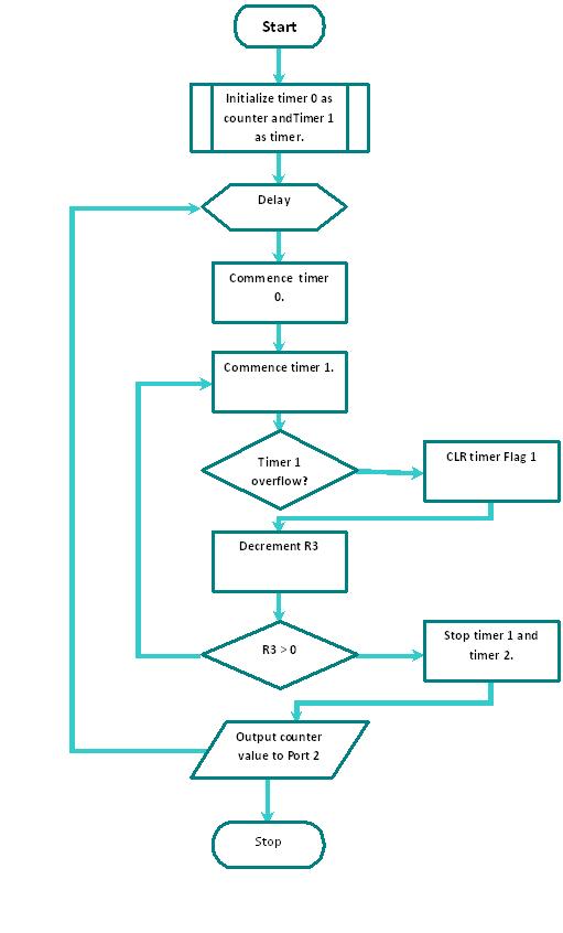
Assembly Code for RMP meter using Mouse Encoder
ORG 0000H
LJMP MAIN
ORG 0030h
MAIN:
MOV TMOD, #15h
MOV P1,#00H
UP:
SETB P1.0
MOV R0,#01FH
OUTER_DE: MOV R1,#0FFH
INNER_DE: DJNZ R1,INNER_DE
DJNZ R0,OUTER_DE
MOV TH1,#00H
MOV TL1,#00H
MOV R3,#02H
MOV TH0,#0FFH
mov TL0,#0FFh
mov P2,#00h
CLR P1.0
SETB TR0
NEXT: MOV A,TL0
CJNE A,#00H, NEXT
SETB TR1
WAIT: JNB TF1,WAIT
CLR TF1
DJNZ R3,WAIT
CLR TR1
CLR TR0
CLR TF1
MOV A,TL0
MOV P2,A
LJMP up
END
C code for parallal port Interfacing
#include
#include
#include
#define data_in 0x378
#define status 0x37A
#define x 25
void main()
{ clrscr();
unsigned char data;
float rev=0.0;
float rpm=0.0;
outportb(status,0x20);
while(1)
{
gotoxy(x,15);
printf("ÉÍÍÍÍÍÍÍÍÍÍÍÍÍÍÍÍÍÍÍÍÍÍÍÍÍÍÍÍÍ»");
gotoxy(x,16);
printf("º ROTATION SPEED METER º");
gotoxy(x,17);
printf("ÌÍÍÍÍÍÍÍÍÍÍÍÍÍÍÍÍÍÍÍÍÍÍÍÍÍÍÍÍ͹");
gotoxy(x,18);
printf("º º");
gotoxy(x,19);
printf("º %7d RPM º",int(rpm));
gotoxy(x,20);
printf("º º");
gotoxy(x,21);
printf("º º");
gotoxy(x,22);
printf("º %7d rad/s º",int((2*(22/7)*rpm)/60));
gotoxy(x,23);
printf("º º");
gotoxy(x,24);
printf("ÈÍÍÍÍÍÍÍÍÍÍÍÍÍÍÍÍÍÍÍÍÍÍÍÍÍÍÍÍͼ");
data= inportb(data_in);
//data=0x01;
rev=(data/45.0);
rpm=(rev*457.77);
}
}
Certificate of ownership:
This is to certify that this project report “ RPM Meter Using Mouse Encoder ”
is the bonafide work of “ Mr.Ahmed Fawad, Mr. M.Asif, Mr. Azeez Ahmed and Mr. M. Zohaib Arif ” of class “ V – OPS/EL – B ” who carried out the project work under my supervision.
Prof. Nazeer Alam
H.O.D ELECTRONICS
Prof. Ikram Rasool Qureshi
SUPERVISOR