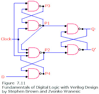
Positive Edge D Flip Flop using 6 NAND gates only
Refer to Master Slave Negative Edge D Flip-flop before you read the next paragraph.
The previously explained circuit was negative edge triggered. The same can be changed into positive edge flipflop by just giving the clock directly to the slave and the complement of it to master. However there is another circuit that accomplishes the same task and requires only 6 NAND gates means fewer transistors and efficient design.
How the above circuit works? ....explained below:
- When clock=0, P1 and P2 are high (i-e P1=P2=1). keeping the values of Q and Q' intact.
- At the same time P4= complement of D and P3=D.
- Now when clock=1 (at positive edge), the values of P3 (equal D) and P4 (complement of D) passes through P1 and P2.
- Now P1=D' and P2=D which means Q=D and Q'=D'

It is also necessary that while clock=1, D must be in don't-care state. Two cases (when clock=1) needs to be studied:
- When D=0, P2=0 which will keep the value of P4=1 regardless of the value of D
- When D=1, P2 and P3 remains high regardless of the value of D.
This implies that the above flip-flop ignores the changes in D when clock=1 (i-e after positive edge of the clock)


