Download the Real time Modulation and Demodulation Models
You can download from the links below:
THEORY
This is the last post of Amplitude and Demodulation using Texas Instrument DSK 6713 and I will try to windup all the important aspects of the term assignment. We have already discussed a simple simulink model of both Amplitude Modulation and Demodulation. You are recommended to see them first. Lets start with the basics.
We will make use of function generator and an oscilloscope. Both will be connected to the TI C6713 on line-in and line-out connectors. Frequency of Carrier Signal is fixed at 15 kHz while the message signal is varried from the function generator. Since DSK C6713 ensures realtime simulation, once the message signal is varied we will see on oscilloscope that modulated signal is also varying. Lets discuss different steps involved.
Block Diagram
C6713 Simulink Model - Amplitude Modulation
• Open a new simulink model and library browser
• Using Embedded Target For TIC6000 DSP menu select C6713 DSK Board Support.
• Using the Embedded Target For TIC6000 DSP tool in the library browser, select C6713 DSK Board Support and add ADC for Line In, DAC for Line Out and Reset Switch. You can extract all these from Simulink Library Browser.
• Implement the simulink model of AM as: You can also download from here.
• Message signal Line in parameters and carrier signal parameters can be set as following. This is very important. Set ADC Source as Line In, Sample Rate 19kHz, Word Length 16-bit. Amplitude :1.
Amplitude of the message signal can be change through function generator (up to 5KHz), whereas, frequency of the carrier signal is 15KHz.
• The output modulated signal observe in oscilloscope is:
C6713 Simulink Model - Amplitude De-Modulation
• Target the device in the similar manner as done above in amplitude modulation.
• A low pass filter has been designed in the FDA Tool in such a way that only the frequency of the message signal (5 KHz) is allow to pass through filter.
• Design the low pass filter using FDA Tool in Matlab.
• Export this filter to the simulink model
• Implement the simulink model of the demodulation. Click to enlarge please or download it from here.
• Run the model and observe the output at the oscilloscope.
CERTIFICATE
This project named “AMPLITUDE MODULATION USING MATLAB SIMULINK AND TEXAS INSTRUMENT KIT C6713”, in all respect is the property of the following personnel who undertake this project as the term project in EE
- Muhammad Ahmed
- Jamal Ahmed
- Muhammad Faisal
For any queries feel free to contact
11:01 |
Posted in
Amplitude Demodulation,
Amplitude Modulation,
c6713,
DSP,
Electronics Projects,
MATLAB,
Matlab Simulink
|
Read More »
What is Music Equalizer ?
Music equalizers are devices or software used for amplifying and attenuating predetermined frequency bands. Every music system, including some portable systems as well as professional stereo systems typically has an equalizer to equalize the audio data. Older system has analog equalizer which was tuned manually, but now a day’s digital music equalizer is very common. The advantage of digital equalizer is that we can store the preset gains of frequencies as desired and can be used in future by just pressing button. An audio equalizer typically will adjust the energy levels of the audio data in one or more different frequency bands in order to change the characteristics of the audio data. The equalizer may generate equalized audio data that may then be converted into analog data so that sound may be generated by a sound generating device, such as a speaker or headphone. The center frequencies for the various filters are distributed across an overall bandwidth having an upper and lower boundary. In general, the analog equalizer includes a combination of a simulated inductor and a bridging amplifier which are constructed of operational amplifiers whereas digital equalizer are made with software and processed by digital signal processor. The same has been accomplished on DSK 6713
Block Diagram of Music Equalizer
Audio Input: The Audio input can be taken from any music player. Mobile phone music player is used as the music input which is feed to DSK 6713 kit through line in connector. Mono channel is used for simplicity.
Analog to Digital Conversion: DSK 6713 has the built in A/D converter which converts the analog input signal into digital signal so that digital processing can be done on the input. The sampling frequency is set to 48kHz. Word length is 16-bit, scaling is normalized and samples per frame are 64. Refer to the diagram below :-
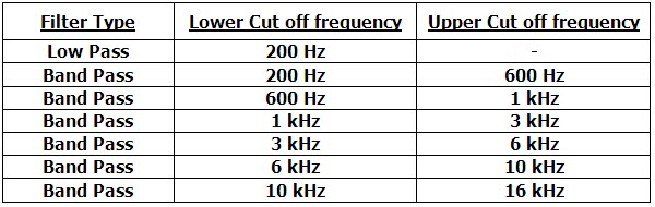
Low and Band Pass Filters for Music Equalizer: Filters are used for separating the signal of different frequencies. One low pass and six band pass filters are designed in MATLAB’s tool, FDATOOL, for filtering seven different bands of frequencies. IIR filters are faster than the FIR filter and give smoother amplitude response as compare to FIR filters. So, IIR filters are used. The key to filters the music correctly is that filter’s cut off frequencies must overlap. The cut off frequencies of all filters are given in table below.
Preset Band Gains for Equalizer: Music effects are produced simply by changing the gains of separated signals of different frequencies. For example, the bass effect is achieved by increasing the gain of lower frequency signals. Preset Band Gain block consists of the 4 set of preset gain which produces Flat, Rock, Bass and Opera Effects. Gain setting for Bass effect is shown below.
Preset Selector: Dip switches on the DSK-6713 are used for preset selection. Zero indexing is used so that normal (flat) preset is selected when no button is pressed. Led on the Kit indicates the preset selection. Parameters of DIP switches are set as shown in figure.
Signal Adder: Signal adder combines all separated signals of different frequencies after completing the processing. Simple adder is used for this purpose.
Digital to Analog Conversion: After the combining, the signal is converted in analog. This is done by DSK 6713 built in D/A converter. The sampling frequency of the A/D and D/A should be same for better output.
SIMULINK MODEL FOR MUSIC EQUALIZER ON DSK 6713
You can download the simulink model for the above equalizer from the link given below, however the snapshot of our working simulink model is given below :
Download Simulink Model for Music Equalizer here.
In case of any problem. feel free to contact at homeofgadgets@yahoo.com
Important Note: This term project of Digital Signal Processing is supervised by Assistant Professor S K Hasnain and is the property of the following students of Pakistan Navy Engineering College (NUST).
- Ahmed Fawad
- Waseem Ahmed
- Aziz Ahmed
- Arslan Amin Dhoraji Wala
For queries please contact at homeofgadgets@yahoo.com
10:34 |
Posted in
c6713,
DSP,
Electronics Projects,
MATLAB,
Matlab Simulink
|
Read More »